| « 1 » | « 2 » | « 3 » | « 4 » | « 5 » | « 6 » | « 7 » | ||||
|---|---|---|---|---|---|---|---|---|---|---|
| < 4-1 > | ||||||||||
| < 4-2 > | ||||||||||
| < 4-3 > | ||||||||||
| < 4-4 > |
|
|
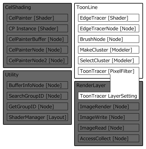
4-2. Toonline Plugin |
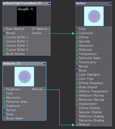
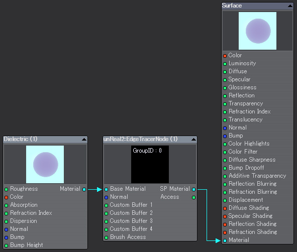
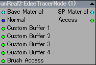
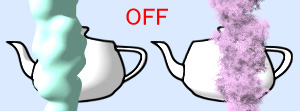
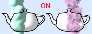
| 2. EdgeTracer Shader Main panel 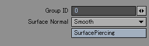 A support of a spreadsheet 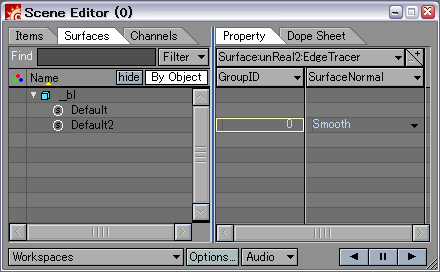 EdgeTracer supports the spreadsheet of a layout. A bank of surface setting has the following. "unReal2:EdgeTracer Buffer"
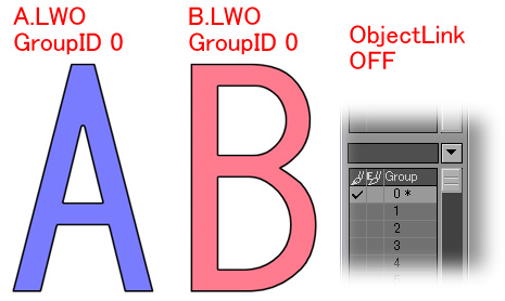
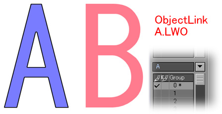
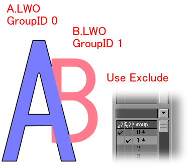
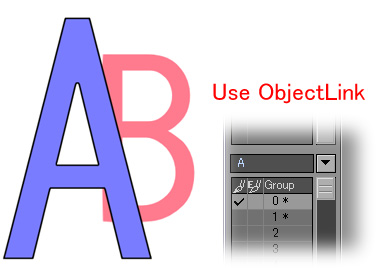
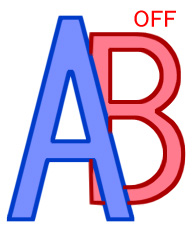
This ID is used in order to be used as a specification for applying setting of ToonTracer or to specify the surface pierced by SurfacePiercing. The span of 0 to 99 can be specified as a value, and the same user ID may be used by two or more surfaces. "Smooth": Use the normal according to smoothing setting of the surface. "Flat": Use the polygon normal which is not interpolated regardless of surface setting. "Smooth+Bump": Output normal also including unevenness of a bump mapping. In this setting, it becomes possible to draw a line on the edge of a bump mapping. Although it was the function offered with the plug-in which became independent as SurfacePiercing shader in the previous version, it was built in EdgeTarcer. 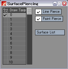 SurfacePiercing enables an expression of the eyebrows which are not hidden in the forelock used by expression of an anime. 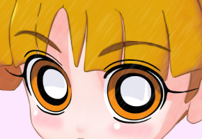 It is the pre-setup for using this function. EdgeTracer shader or EdgeTracerNode is set to both the surface which wants to pierce and draw to foregrounds, such as eyebrows, and the surface which permits penetration of forelock etc. And a different group-ID from other surfaces is set to the surface by the side of eyebrows which wants to draw, and the ID is checked for a drawing by SurfacePiercing setting by the side of forelock. It is an example of a setups of the aforesaid image. The surface of eyebrows and eyes is a group-ID = 1. The target for a drawing of SurfacePiercing set as hair also checks 1. The other surface is a group-ID = 0.
|
| 4. BrushNode Node 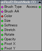 Main panel 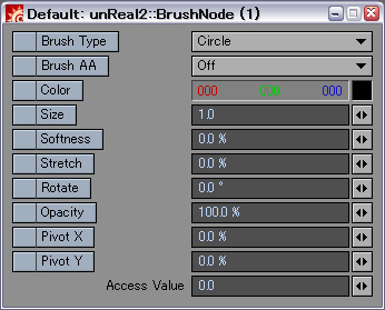 BrushNode can set up a local brush effective only in the set surface. Only the topic which enabled the checkbox of the brush parameter name is used. For example, only the color of a line is changed by BrushNode, and only the check of "Color" enables other setting to use the thing of ToonTracer. Refer to the instruction of ToonTracer for the details of each brush parameter. Moreover, please connect Access of an output to Brush Access of EdgeTracerNode. |
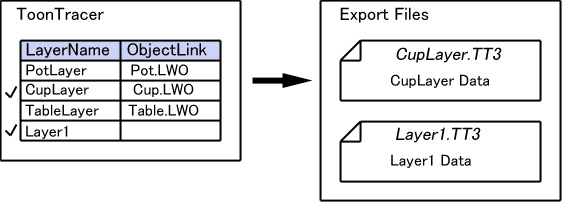
| 7. ToonTracer Pixelfilter Main panel  ToonTracer is a plug-in which takes charge of a drawing of a line, detects the section which serves as an outline and a boundary line from the buffer created by EdgeTracer at the time of a rendering, and draws a line using a brush.
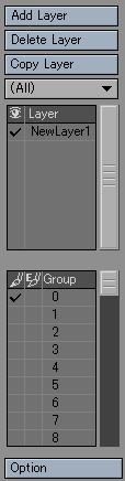 ToonTracer handles brush setting and drawing setting as one layer. It also becomes possible to draw an object and the line of different setting for each surface by using two or more layers. An edit of these layer list and a selection are done in a layer edit area.
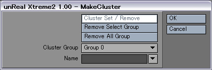
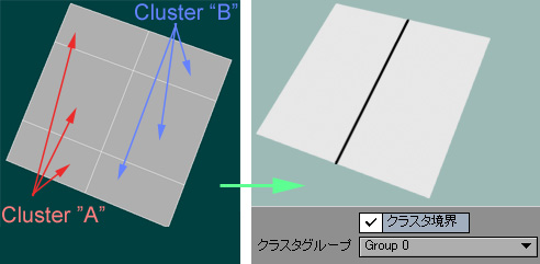
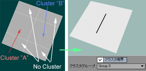
In this area, it can be set up to which GroupID the selected layer draws, or whether it excludes from a drawing.
Details here |
Layer setup area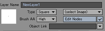 In this area, the layer under selection is set up by a layer list.
It can be used to the half-width alphanumerical of 80 characters.
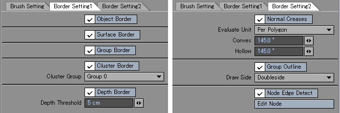
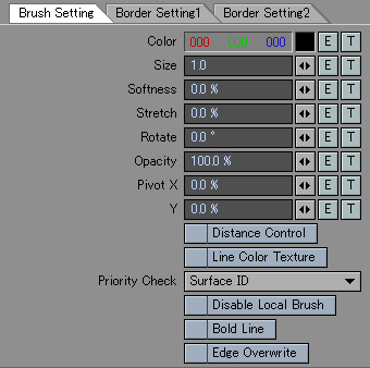 The detailed drawing style of a brush is set up in this tab.
|
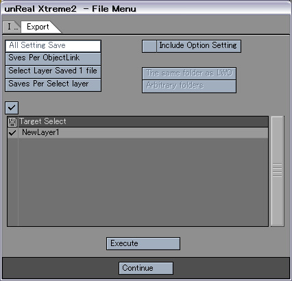
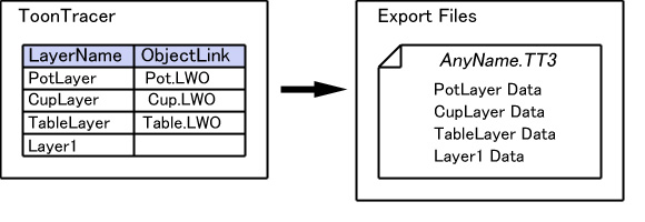
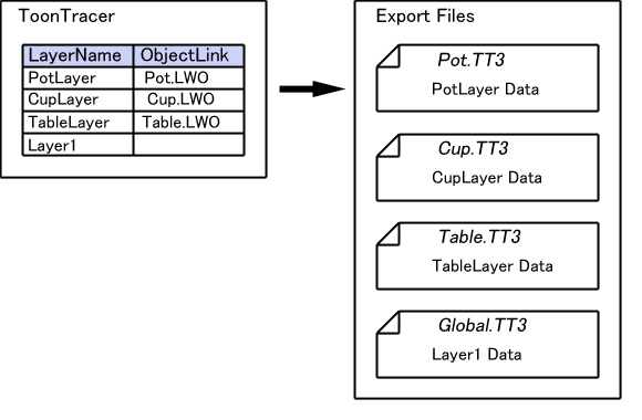
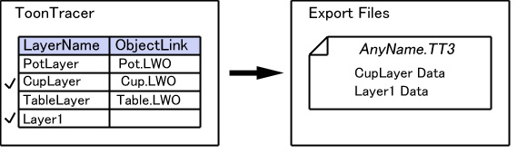
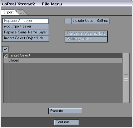
| Option setups area An option area does overall setting of ToonTracer and RenderLayer Images.
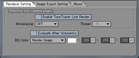
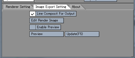
Moreover, it can access to utilities, such as save of setting. 
|
Surface List panel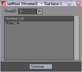 The list of surface names with arbitrary GroupID is displayed as this panel. It can work checking a surface and a GroupID at the time of setting of ToonTracer and SurfacePiercing. |
| ∧ Top ∧ |