|
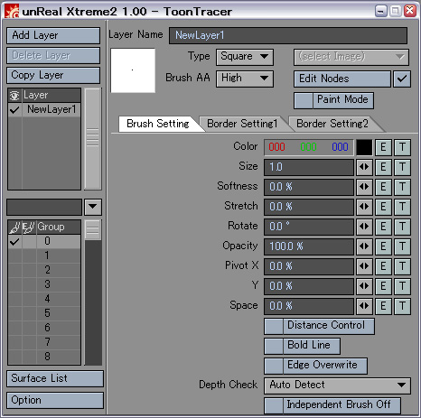
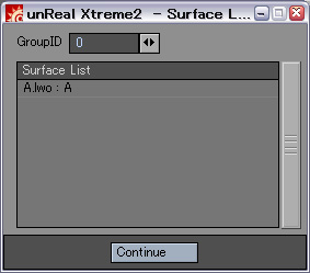
Layer setup area
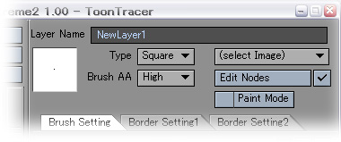
In this area, the layer under selection is set up by a layer
list.
- Layer Name
It is a name displayed on a layer list.
It can be used to the half-width alphanumerical of 80 characters.
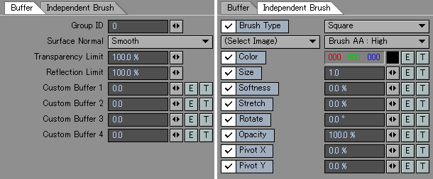
- Brush basic setups area
In this area, the form used as the base of the brush used for a drawing
of a line etc. is set up.
- Type
The form of a brush is selected.
"Circle": circle.
"Square": Square
"Image": Any images can be used from a right popup.
- Brush AA
Except standard antialiasing setting, antialiasing by oversampling is
applied to the brush pattern itself at a generate time.
It is effective, when having set the degree of rotation angle as a brush,
or especially when having opened the drawing space character greatly.
- Edit Nodes (LW9)
A brush parameter can be set using a node system.
However, a part of nodes currently made only for shader may not work
normally.
- Paint Mode
If this check is validated, it will become a mode which smears away
not a line but the specified surface of a GroupID.
- Brush setup tab
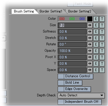
The detailed drawing style of a brush is set up in this tab.
- Color
It is a color of a brush.
- Size
The size of a brush is set up by a pixel measure.
- Softness
It becomes so thin that the gray level of a brush will go outside if
a value is enlarged.
- Stretch
If a value is enlarged, a brush will be shrunk by a lengthwise direction.
- Rotate
An angle is applied to a brush.
- Opacity
The opacity of a brush is set up.
- Pivot X
- Pivot Y
The center of a brush is shifted at the percentage to a brush size.
At 100%, it shifts by one brush and is drawn.
- Space
The drawing space of a line is set up.
However, if it uses together with antialiasing of a camera, it will
not be drawn normally.
- Distance Control
A brush size can be changed according to distance using a gradient texture.
- Bold Line
If this check is validated, a thin line will be drawn thickly a little.
- Edge Overwrite
When drawing a line with two or more layers, a line is not overwritten
at the section by which the line was usually already drawn with the
front layer.
If this check is validated, that layer will be overwritten also in the
section by which the line is already drawn.
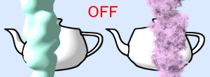
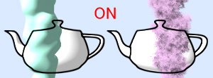
- Depth Check
Usually, the pixel does not take a detection processing of a line into
consideration to which is in a foreground within 3D scene in order to
check the pixel which adjoins each other toward a lower-right from a
upper left.
However, the right result is not obtained unless it gives priority to
the data on the pixel in a foreground, when the control using pixel
data is done in the independent brush and brush parameter which were
set as the surface using a texture.
It is set up whether a depth check checks a relationship around the
pixel, and does an outline detection.
However, shakiness happens on the line of the section which has caved
in by which the polygon intersects that a processing time increases
a little when a depth check is validated.
"Auto Detect": Confirm whether the texture is used for the brush parameter
and set up ON and OFF automatically.
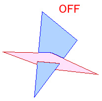
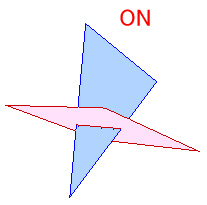
"Always OFF","Always ON" : setting is fixed regardless of brush parameter.
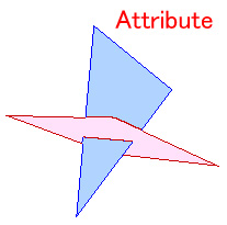
"Attribute Only": it is a special mode and is a mode which validates
a depth check, suppressing the shakiness of a line which occurs in the
transposition section of the above-mentioned polygons.
- Independent Brush Off
Whenever it validates this check, brush setting set up by EdgeTracer
is disregarded and layer setting is used.
- Border Setting 1, 2 tab
The requirements of a border section of generating a line are set up in
the tab of demarcation.
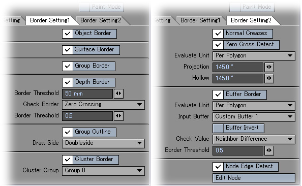
- Object Border
A line is drawn into the border sections of an object and a background,
and a different border section of objects.
- Surface Border
A line is drawn into the border section of a different surface.
The surface name of the same name in a different object is also handled
as another surface.
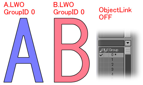
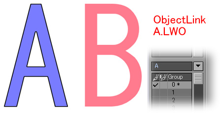
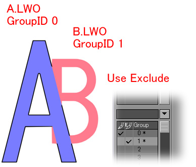
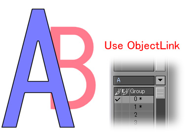
- Group Border
A line is drawn into the border section with a different GroupID of
a surface.
- Depth Border
The depth of an adjacent pixel is measured and a line is drawn into
a section with the difference more than fixed.
- Depth Threshold
When the depth is separated greater than the specified distance, it
is the drawing target of a line.
- Check Border
The requirements which check a depth border are selected.
"Polygon Border" checks only in the border section of a polygon.
"Polygon Set" checks only in a section only by the section from which
the Polygonset in which a polygon belongs differs.
"CustomBuffer 1 to 4" checks only in the section in which the difference
greater than the value of a check threshold has a value of the specified
Custom buffer.
"Zero Crossing" calculates the amount of transitions of a depth with
an neighborhood pixel, and checks only in the intense section of a
transition.
"Cluster Group 0 to 3" checks only in the section from which the cluster
name of the specified cluster group differs.
- Check Threshold
It is a finding threshold used when a "Custom Buffer" is specified
on a check border.
- Group Outline
A line is drawn for the group which drew effectively for the outline
as one cluster.
- Draw Side
"Doubleside": Draw the normal line.
"Inside": Draw a brush pattern only inside from a drawing border section.
"Outside": Draw a brush pattern only outside from a drawing border
section.
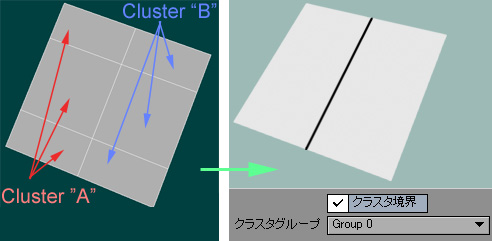
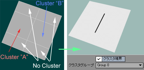
- Cluster Border
A line is drawn on the border of a section where the cluster names of
the cluster set up by the modeler differ.
However, a line does not draw in the border of the polygon under a cluster,
and the polygon which does not belong to a cluster.
- Cluster Group
The cluster group used as the target for a check is specified.
A cluster border checks the clusters of the same group.
- Normal Creases
The angle of the normal of an adjacent pixel is checked and a line is drawn into the section which is an acute angle from the threshold.
- Zero Cross Detect
The amount of transitions of a normal angle with a neighborhood pixel is calculated, and it checks only in the intense section of a transition.
- Evaluate Unit
"Per Polygon" checks only in the border section of polygons.
"Per Pixel" checks by the pixels after a rendering.
Therefore, although a processing becomes slow, it can draw a line also to unevenness of a bump map.
- Convex
A border section sets up the threshold of the section which is a mountain fold.
- Hollow
A border section sets up the threshold of the section which is a valley fold.
Since it will be the drawing target of a line unconditionally if it is set as 180 degrees, a wireframe can be drawn, if a validation unit of measure is performed per polygon and a threshold is performed into 180 degrees also with a mountain and a valley.
- Buffer Border
A line is drawn using the value of a Custom Buffer.
- Evaluate Unit
"Per Polygon" checks only in the border section of polygons.
"Per Pixel" checks by the pixels after a rendering.
- Input Buffer
The Custom Buffer used for the check of a value is selected.
- Buffer Invert
It is used inverting the value of a Custom Buffer.
- Check Value
"Neighbor Difference": Compare the adjacent absolute value and threshold of a difference of pixels.
"Pixel Value": Use the buffer value of a pixel for comparison as it is.
- Border Threshold
A line is drawn when a check value becomes more than this threshold.
- Node Edge Detect
A line can be freely drawn using a node system.
The input of the root node serves as an integer value, and a line is drawn in case of one or more values.
|